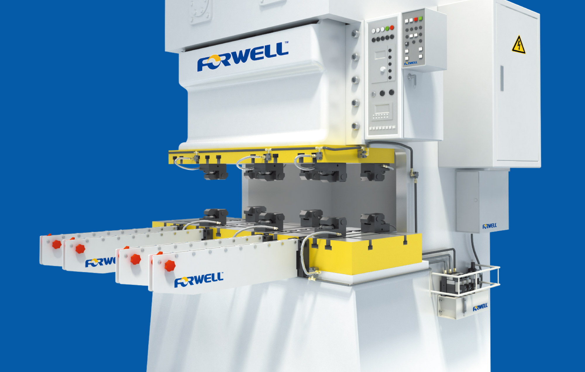
For many manufacturers, such as automobile and aircraft manufacturers, press machines form a vital part of the production cycle. This means that there is an increased reliance on the efficiency and productivity of press machines whilst maintaining high levels of consistency and precision. One aspect that is often overlooked is the arduous process of operating a press machine, which includes long hours of constant supervision, painstaking maintenance, and also very annoying die changes.
Forwell’s wide selection of customizable quick die change systems and accessories is the perfect partner for any press machine as it not only speeds up die change time but also greatly simplifies operations for the operator. This is because automatic die clamps and easy to use die lifters facilitate the easy exchange of press machine dies. As Forwell’s products use standardized dies, die changing is fast and easy, thereby increasing operator safety and improving the work environment. For the work floor looking to boost their productivity even more, Forwell’s die change systems can be coupled with a die cart system to fully automate the die changing process of multiple press machines.
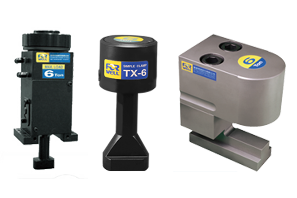
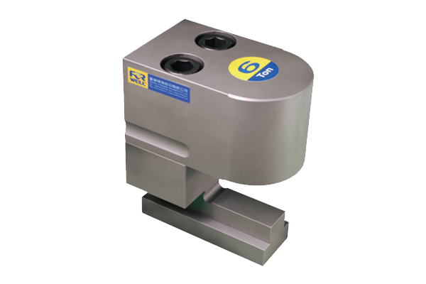
All Forwell Quick Mold Change Systems use high quality Die Clamps for very secure clamping, quick mold changing and safer operations. These clamps can fasten Molds whether they are changed vertically or horizontally.
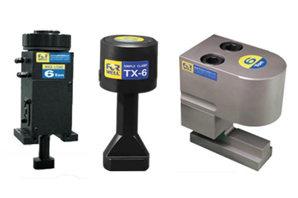
There are also a range of different Die Clamps available to suit your injection molding or mold casting requirements. The TY type Die Clamps are machined to fit into the T-slot of the bolster for extra secure positioning. The flange-mount model Die Clamps can be bolted onto the bolster and the automatic slider model Die Clamps makes remote automatic operation possible.
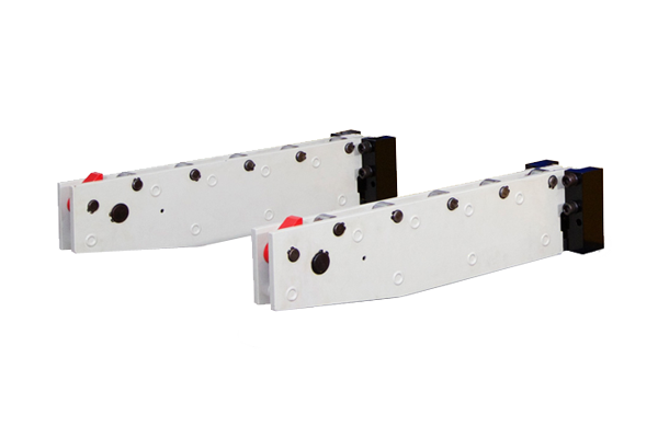
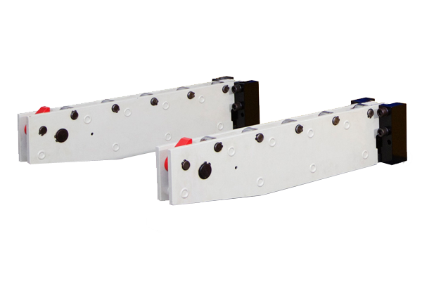
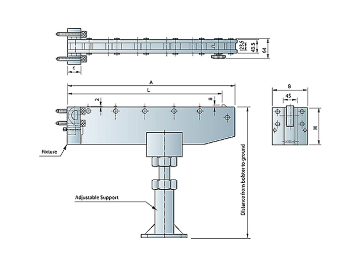
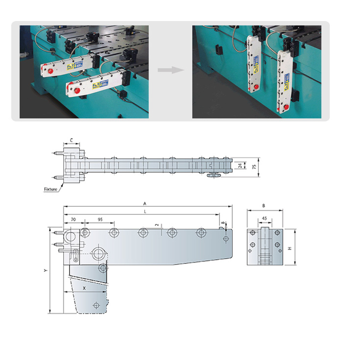
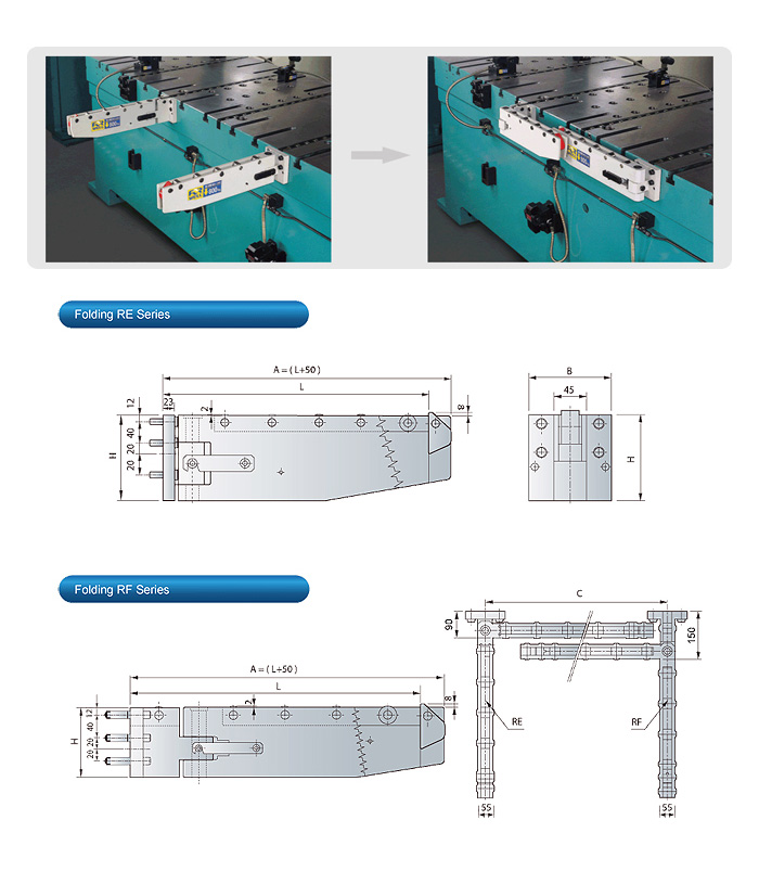
Bolster extensions or Die Arms make it very easy and simple to pull out or push a die in. It also allows for a forklift or crane to remove and load dies easily. Die stoppers at the end of each Die Arm will prevent the die from rolling off but at the same time provide easy die loading onto the bolster extensions.
The Die Arms are equipped with hardened rollers to allow for a long service life and accurate die loading. The Die Arms can be selected according to carrying capacity, and are available in three different types: RC detachable type, RD drop-down type and RE/RF folding type.
The bolster extension makes it easy to move the dies to an accessible area of the press for convenient die changing with a crane or forklift truck. Available in three different designs: detachable RC series, drop-down RD series(alternate model), and folding RE/RF series.
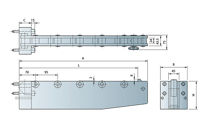
Model | Die Travel(L) | Max.Load ( kg ) | Overall Length ( A ) |
---|---|---|---|
RC-500-800 | 500 | 800 | 550 |
RC-500-1250 | 500 | 1250 | 550 |
RC-500-1600 | 500 | 1600 | 550 |
RC-700-600 | 700 | 600 | 750 |
RC-700-1000 | 700 | 1000 | 750 |
RC-800-800 | 800 | 800 | 850 |
RC-800-1600 | 800 | 1600 | 850 |
RC-800-2000 | 800 | 2000 | 850 |
RC-900-900 | 900 | 900 | 950 |
RC-1000-1600 | 1000 | 1600 | 1050 |
Model | Fixture | Rollers | Installed Dimensions | Fixture Model | ||
---|---|---|---|---|---|---|
B | C | H | ||||
RC-500-800 | 115 | 46 | 120 | 5 | A type | RC-120 |
RC-500-1250 | 160 | RC-160 | ||||
RC-500-1600 | 50 | 200 | B type | RC-200 | ||
RC-700-600 | 46 | 120 | 7 | A type | RC-120 | |
RC-700-1000 | 160 | RC-160 | ||||
RC-800-800 | 160 | 8 | ||||
RC-800-1600 | 50 | 200 | B type | RC-2000 | ||
RC-800-2000 | 240 | RC-240 | ||||
RC-900-900 | 200 | 9 | RC-200 |
Model | Die Travel(L) | Max.Load ( kg ) | Overall Length ( A ) |
---|---|---|---|
RC-1200-2500 | 1200 | 2500 | 1250 |
RC-1300-2500 | 1300 | 2500 | 1350 |
RC-1400-2500 | 1400 | 2500 | 1450 |
RC-1500-2500 | 1500 | 2500 | 1550 |
RC-1600-2500 | 1600 | 2500 | 1650 |
RC-1700-2500 | 1700 | 2500 | 1750 |
Requires adjustable support if die travels over 1000mm. These models come standard with adjustable support.
Contact us for other specifications.
Model | Fixture | Rollers | Installed Dimensions | Fixture Model | ||
---|---|---|---|---|---|---|
B | C | H | ||||
RC-1200-2500 | 115 | 45 | 120 | 14 | A type | RC-120 |
RC-1300-2500 | 15 | |||||
RC-1400-2500 | 17 | |||||
RC-1500-2500 | 18 | |||||
RC-1600-2500 | 19 | |||||
RC-1700-2500 | 20 |
Model | Die Travel(L) | Max.Load ( kg ) | Overall Length ( A ) |
---|---|---|---|
RD-500-800 | 500 | 800 | 550 |
RD-500-1250 | 500 | 1250 | 550 |
RD-500-1600 | 500 | 1600 | 550 |
RD-700-600 | 700 | 600 | 750 |
RD-700-1000 | 700 | 1000 | 750 |
RD-800-800 | 800 | 800 | 850 |
RD-800-1600 | 800 | 1600 | 850 |
RD-800-2000 | 800 | 2000 | 850 |
RD-900-900 | 900 | 900 | 950 |
RD-1000-1600 | 1000 | 1600 | 1050 |
Model | Fixture | Rollers | Installed Dimensions | Drop-Down | |||
---|---|---|---|---|---|---|---|
B | C | H | X | Y | |||
RD-500-800 | 115 | 52 | 120 | 5 | A type | 140 | 620 |
RD-500-1250 | 160 | 180 | 660 | ||||
RD-500-1600 | 200 | B type | 220 | 700 | |||
RD-700-600 | 120 | 7 | A type | 140 | 850 | ||
RD-700-1000 | 120 | 180 | 860 | ||||
RD-800-800 | 160 | 8 | 180 | 960 | |||
RD-800-1600 | 200 | B type | 220 | 1000 | |||
RD-800-2000 | 240 | 260 | 1040 | ||||
RD-900-900 | 200 | 9 | 220 | 1100 | |||
RD-1000-1600 | 10 | 1200 |
Model | Die Travel(L) | Max.Load ( kg ) | Overall Length ( A ) |
---|---|---|---|
RE.RF-500-800 | 500 | 800 | 550 |
RE.RF-500-1250 | 500 | 1250 | 550 |
RE.RF-700-600 | 700 | 600 | 750 |
RE.RF-700-1600 | 700 | 1600 | 750 |
RE.RF-800-800 | 800 | 800 | 850 |
RE.RF-800-1600 | 800 | 1600 | 850 |
RE.RF-500-1600 | 500 | 1600 | 550 |
RE.RF-900-900 | 900 | 900 | 950 |
Model | Fixture | Rollers | Installed Dimensions | Drop-Down | |||
---|---|---|---|---|---|---|---|
B | C | H | X | Y | |||
RE.RF-500-800 | 525 | 115 | 120 | 5 | A type | 90 | 150 |
RE.RF-500-1250 | 525 | 160 | |||||
RE.RF-700-600 | 725 | 120 | 7 | ||||
RE.RF-700-1600 | 725 | 200 | 7 | B type | |||
RE.RF-800-800 | 825 | 160 | 8 | A type | |||
RE.RF-800-1600 | 825 | 200 | 8 | B type | |||
RE.RF-500-1600 | 525 | 5 | |||||
RE.RF-900-900 | 925 | 9 |
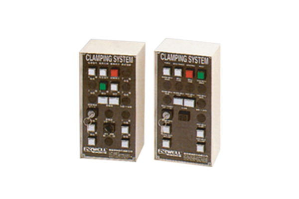
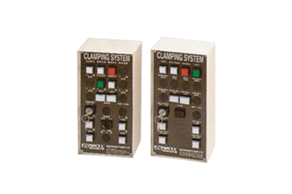
The easy to use control panel offers a simple interface to monitor and control operations of the Quick Mold Change System. The upper half of the screen displays automatic functions while the lower half can be used for operator-controlled functions. This makes this machine easy to control yet still have the functionality needed of a Quick Mold Change System.
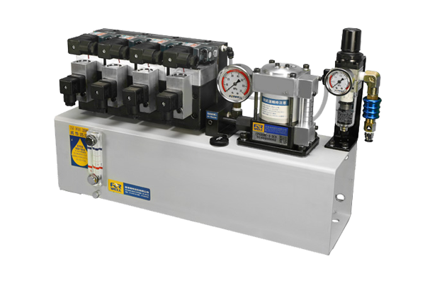
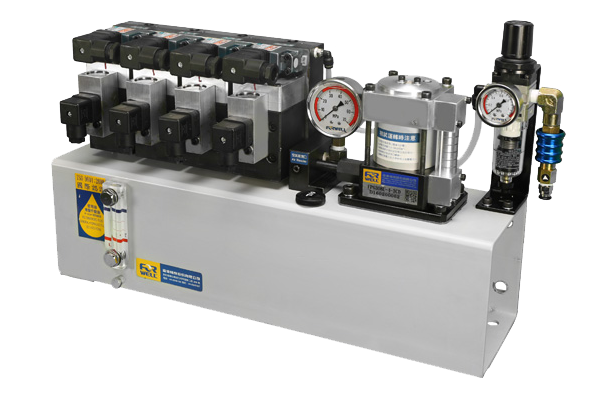
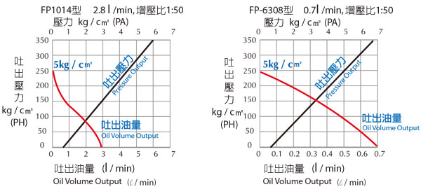
The hydraulic pump ensures tight and stable die clamping and allows the system to maintain clamping pressure on the mold even when there is a power failure or air pressure drops. The PCB Fine Piercing System uses air-driven hydraulic pumps resulting in very high clamping pressures, high energy efficiency and convenient automated operations. Forwell’s hydraulic pump units also feature an easy to adjust air pressure valve to effectively control the systems air pressure.
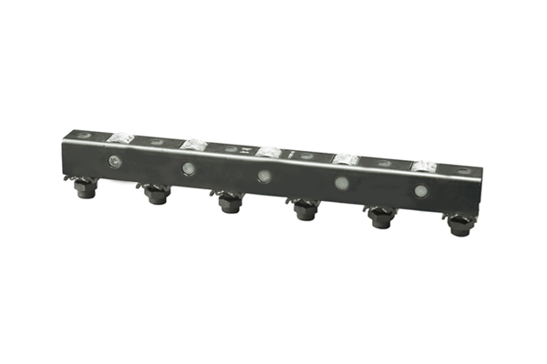
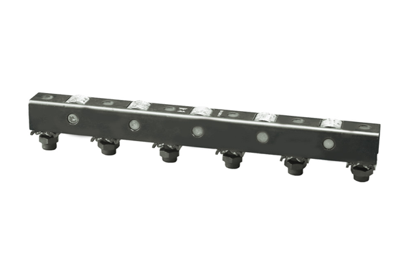
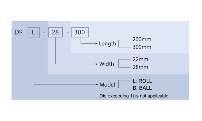
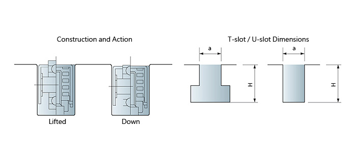
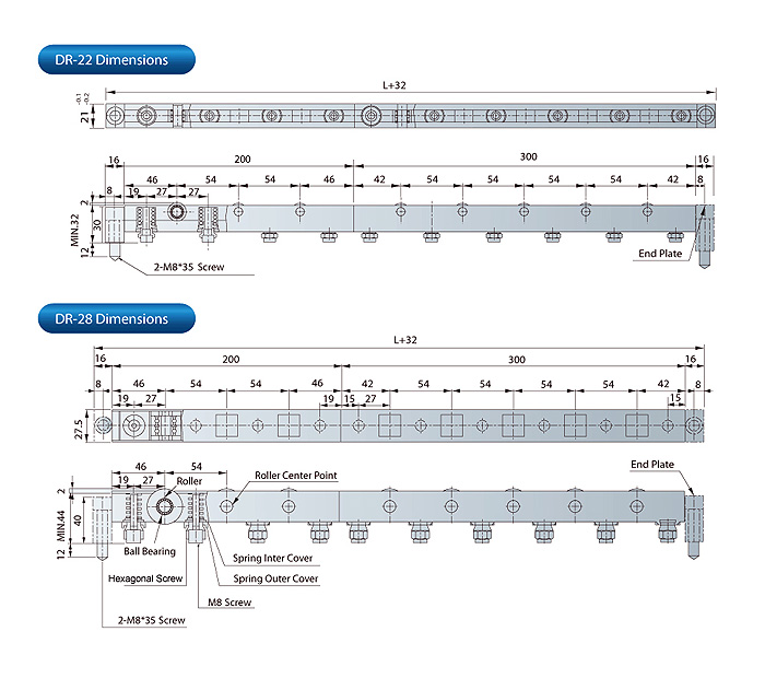
These Spring-Loaded Die Lifters easily slide into different sized T or U-slots on the bolster by adding spacers to the side walls of the Die Lifters. This allows for accurate and easy die positioning as well as quick and easy die removal. The DR Series Die Lifters are available in customizable lengths in increments of 100mm, and are available as either a ball type lifter or roller type lifter.
Model | a | H |
---|---|---|
DR-22 | 22 | 33-43 |
DR-28 | 28 | 45-58 |
Basic Model | Width (mm) | Length (mm) | Springs (pcs) | Lift Farce (kgf) |
---|---|---|---|---|
DRL-22-200/DRB22-200 | 22 | 200 | 4 | 37.5 |
DRL-22-300/DRB22-300 | 22 | 300 | 6 | 37.5 |
DRL-28-200/DRB28-200 | 28 | 200 | 4 | 75 |
DRL-28-300/DRB28-300 | 28 | 300 | 6 | 75 |
Maximum lift force per line (kgf)
mm kgf Model |
200 | 300 | 400 | 500 | 600 | 700 | 800 | 900 | 1000 |
---|---|---|---|---|---|---|---|---|---|
DR-22 | 150 | 225 | 300 | 375 | 450 | 525 | 600 | 675 | 750 |
DR-28 | 300 | 450 | 600 | 750 | 900 | 1050 | 1200 | 1350 | 1500 |
Maximum lift force per line (kgf)
mm kgf Model |
1100 | 1200 | 1300 | 1400 | 1500 | 1600 | 1700 | 1800 | 1900 | 2000 |
---|---|---|---|---|---|---|---|---|---|---|
DR-22 | 825 | 900 | 975 | 1050 | 1125 | 1200 | 1275 | 1350 | 1425 | 1500 |
DR-28 | 1650 | 1800 | 1950 | 2100 | 2250 | 2400 | 2550 | 2700 | 2850 | 3000 |
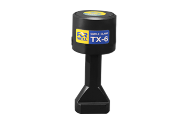
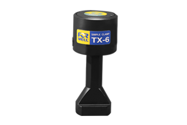
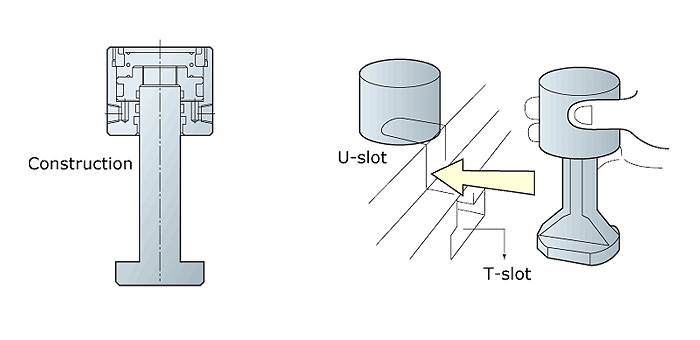
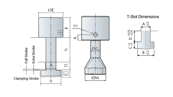
This compact, space saving, piston type clamp requires U-slots on the die shoe. The clamp leg is machined to fit the T-slot on the bolster. With the TX Die Clamp automatic slide model remote control is made possible.
Model | Unit | TX-1 | TX-2 | TX-4 | TX-6 | TX-10 | TX-16 | TX-25 |
---|---|---|---|---|---|---|---|---|
Clamping Farce(at 250kgf/cm2) | tons | 1 | 2 | 4 | 6.3 | 10 | 16 | 25 |
Full Stroke (X) | mm | 5 | 8 | 8 | 8 | 8 | 8 | 8 |
Clamping Stroke (Y) | mm | 2.5 | 4 | 3 | 3 | 3 | 3 | 3 |
Extra Stroke (Z) | mm | 2.5 | 4 | 5 | 5 | 5 | 5 | 5 |
Cylinder Capacity at Full Stroke | cc | 2.7 | 6.5 | 13 | 21 | 32 | 54 | 84 |
Extra stroke is the difference between full stroke and clamping stroke with extra space allowed for safe operation.
Model | E | F | G | H | K | MIN. | PT |
---|---|---|---|---|---|---|---|
TX-1 | 38 | 37 | 14 | 35 | 11 | 8 | 1/8 |
TX-2 | 53 | 52.5 | 18 | 38 | 12 | 8 | 1/8 |
TX-4 | 68 | 61.5 | 23 | 59 | 15 | 10 | 1/4 |
TX-6 | 78 | 68 | 27 | 59 | 16 | 14 | 1/4 |
TX-10 | 98 | 71 | 38 | 79 | 16 | 17 | 1/4 |
TX-16 | 127 | 78.5 | 48 | 88 | 16 | 20 | 1/4 |
TX-25 | 148 | 100 | 58 | 98 | 15 | 23 | 1/4 |
Die shoe thickness(h)Classify:25、30、35、40、45、50、55、60mm.
Before purchase, please verify mold edge thickness (h) and T-slot (A.B.C.D.) has standard or special dimensions.
Model | A | B | C | D | Power Unit Models |
---|---|---|---|---|---|
TX-1 | 22 | 37 | 16 | 24 | FP6308U-口-口 |
TX-2 | 22 | 37 | 16 | 24 | |
TX-4 | 22 | 37 | 16 | 24 | |
TX-6 | 28 | 48 | 20 | 28 | |
TX-10 | 28 | 48 | 20 | 28 | FP1014U-口-口 |
TX-16 | 28 | 48 | 23 | 28 | |
TX-25 | 36 | 56 | 25 |
Die shoe thickness(h)Classify:25、30、35、40、45、50、55、60mm.
Before purchase, please verify mold edge thickness (h) and T-slot (A.B.C.D.) has standard or special dimensions.
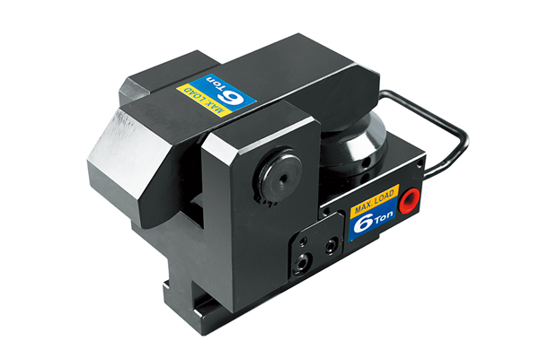
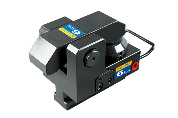
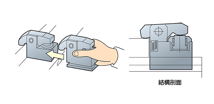
As this lever-type clamp does not require a U-slot on the die shoe it can be used in a wide range of applications. The TY type Die Clamps are machined to fit into the T-slot of the bolster for extra secure positioning. The flange-mount model Die Clamps can be bolted onto the bolster and the automatic slider model Die Clamps makes remote automatic operation possible.
All Forwell Quick Mold Change Systems use high quality Die Clamps for very secure clamping, quick mold changing and safer operations. These clamps can fasten Molds whether they are changed vertically or horizontally.
There are also a range of different Die Clamps available to suit your injection molding or mold casting requirements. The TY type Die Clamps are machined to fit into the T-slot of the bolster for extra secure positioning. The flange-mount model Die Clamps can be bolted onto the bolster and the automatic slider model Die Clamps makes remote automatic operation possible.
The following specifications can help you choose the appropriate clamp type in accordance with your injection molding requirements and production situation. Make sure of your production plans and production procedure before choosing your product to be sure of the product that best suits your needs.
Mold Plate | Mold Change Direction | Clamping type | Characteristics |
---|---|---|---|
No Union | Vertically | Moving Clamp | Fixed in with T-slot |
Union | Vertically | Fixed & Moving Clamp | Clamp fixed or Moving on plate |
Horizontally | Fixed Clamp | Install roller or sliding rail upon the plate. Use cart or mold exchange table for easy operation and the shortest possible mold changing time. |
Model | Unit | TY-1 | TY-2 | TY-4 | TY-6 | TY-10 | TY-16 | TY-25 |
---|---|---|---|---|---|---|---|---|
Tons Clamping (at 250Kg/cm2) | tons | 1 | 2 | 4 | 6.3 | 10 | 16 | 25 |
Full Stroke (X) | mm | 6 | 7 | 7 | 8 | 8 | 7 | 8 |
Clamping Stroke (Y) | mm | 3 | 2 | 3 | 4 | 3 | 3 | 3 |
Extra Stroke (Z) | mm | 3 | 5 | 4 | 4 | 5 | 4 | 5 |
Cylinder Capacity st Full Stroke | cc | 2 | 6.5 | 13.2 | 22.3 | 37 | 61 | 93 |
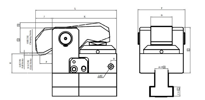
For a closer look at the exact dimensions of the TY series die clamps please see the following diagram and table.
Model | min.E | F | G | J | K | L | max.N | P | R | min.S | PT | min.C | min.A |
---|---|---|---|---|---|---|---|---|---|---|---|---|---|
TY-1 | 49.5 | 46 | 20 | 15 | 58 | 73 | 10 | 10 | 34 | 16.5 | 1/8 | 7 | 10 |
TY-2 | 59 | 63 | 28 | 22 | 85 | 107 | 10 | 12.5 | 48 | 27 | 1/8 | 9.5 | 12.5 |
TY-4 | 85 | 87 | 40 | 25 | 120 | 145 | 10 | 16 | 12 | 32 | 1/4 | 12 | 15 |
TY-6 | 94 | 97 | 44 | 29.5 | 133 | 162.5 | 11 | 20 | 12 | 40 | 1/4 | 14 | 19 |
TY-10 | 105 | 110 | 50 | 28 | 165 | 193 | 11 | 20 | 19 | 53 | 1/4 | 16.5 | 23 |
TY-16 | 120 | 130 | 60 | 30 | 200 | 230 | 12 | 20 | 25 | 67 | 1/4 | 19 | 27 |
TY-25 | 133 | 150 | 73 | 30 | 240 | 270 | 13 | 20 | 30 | 81 | 1/4 | 22 | 32 |
Model | A | B | C | D | Power Unit Models |
---|---|---|---|---|---|
TY-1 | 22 | 37 | 16 | 24 | FP6308U-4-4C |
TY-2 | 22 | 37 | 16 | 24 | |
TY-4 | 22 | 37 | 16 | 24 | FP1014U-4-4C |
TY-6 | 28 | 48 | 20 | 28 | |
TY-10 | 28 | 48 | 20 | 28 | |
TY-16 | 28 | 48 | 23 | 28 | |
TY-25 | 36 | 56 | 25 | 28 |
Die shoe thickness (h) available: 25, 30, 35, 40, 45, 50, 55, 60mm.
Before purchasing, please verify if the mold edge thickness (h) and T-slot (A.B.C.D.) have standard or special dimensions.
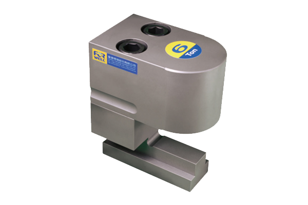
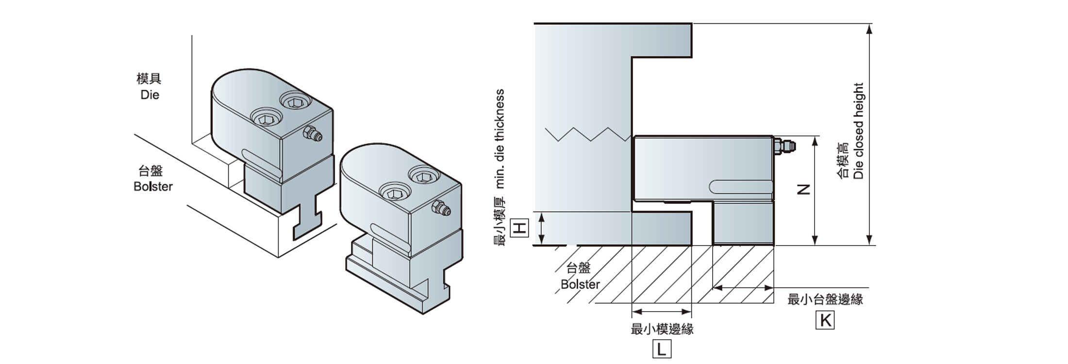
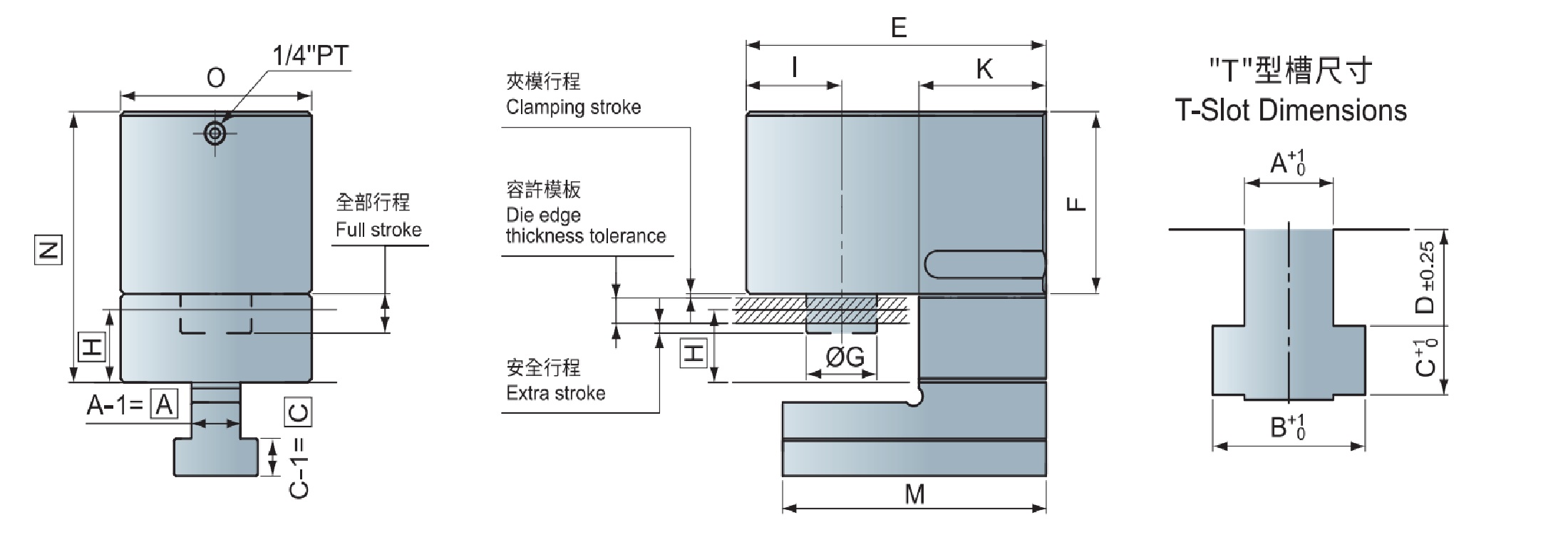
This vertical type clamp does not require a U-slot on the die shoe.The clamping stroke will be longer.
Model | TD-2 | TD-4 | TD-6 | TD-10 |
---|---|---|---|---|
Clamping Force ( at 250 kg / cm2 ) ( tons ) | 2 | 4 | 6.3 | 10 |
Full Stroke ( X ) ( mm ) | 13 | 15 | 15 | 20 |
Flamping Stroke ( Y ) ( mm ) | 9 | 10 | 10 | 15 |
Extra Stroke ( Z ) ( mm ) | 4 | 5 | 5 | 5 |
Cylinder Capacity st Full Stroke ( cc ) | 12.5 | 30 | 42.5 | 89 |
Extra stroke is the difference between full stroke and clamping stroke with extra space allowed for safe operation.
Model | min.H | min.L | min.K |
---|---|---|---|
TD-2 | 15 | 38.5 | 50 |
TD-4 | 24 | 54 | 58 |
TD-6 | 29 | 59 | 63 |
TD-10 | 29 | 72 | 70 |
Notice if ”N ”size is suitable for the die in closed condition.
Model | E | F | G | I | K | M | O | min.N | min.A | min.C | A | B | C | D | Power Unit |
---|---|---|---|---|---|---|---|---|---|---|---|---|---|---|---|
TD-2 | 107 | 57 | 17 | 30 | 50 | 102 | 61 | F+25 | 12.5 | 9.5 | 22 | 37 | 16 | 24 | FP6308U-☐-☐ |
TD-4 | 130 | 63 | 28 | 40 | 58 | 120 | 80 | F+35 | 15 | 12 | 22 | 37 | 16 | 24 | FP1014U-☐-☐ |
TD-6 | 145 | 68 | 28 | 45 | 63 | 130 | 90 | F+40 | 19 | 14 | 28 | 48 | 20 | 28 | |
TD-10 | 165 | 92.5 | 39 | 52.5 | 70 | 145 | 105 | F+45 | 23 | 16.5 | 28 | 48 | 20 | 28 |
Before purchase, please verify mold edge thickness (h) and T-Slot(A.B.C.D) has standard or special dimensions.