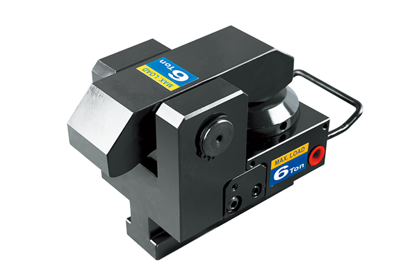
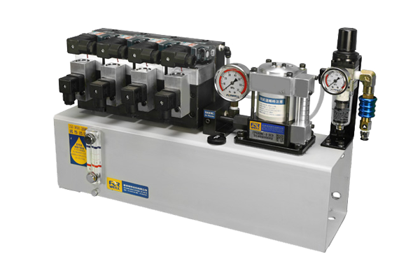
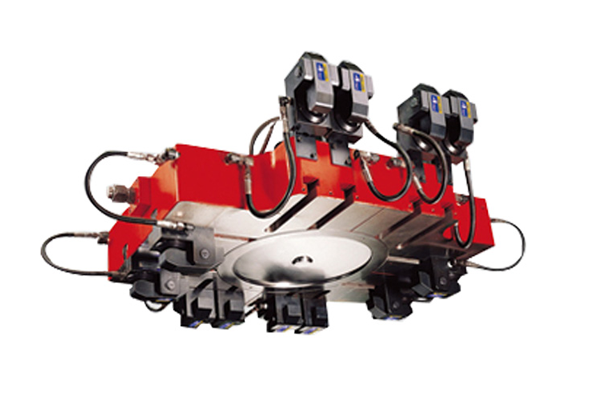
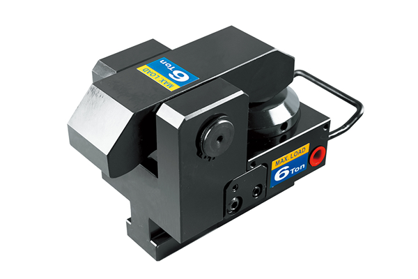
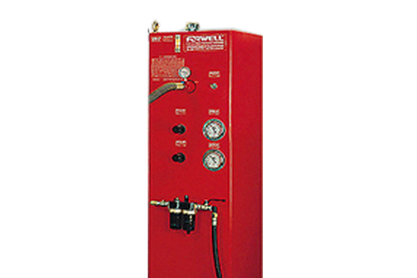
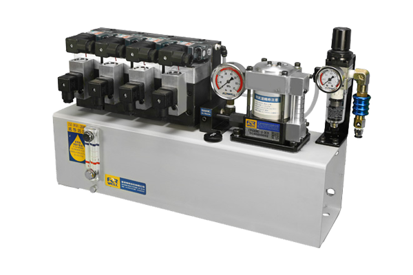
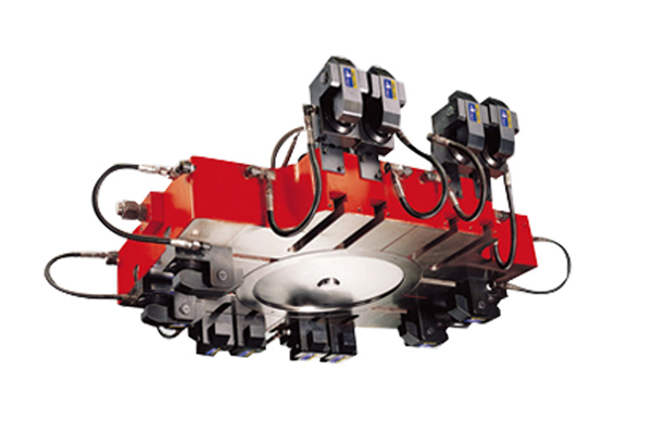
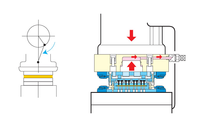
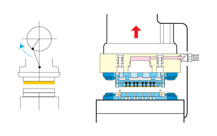
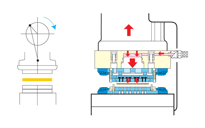
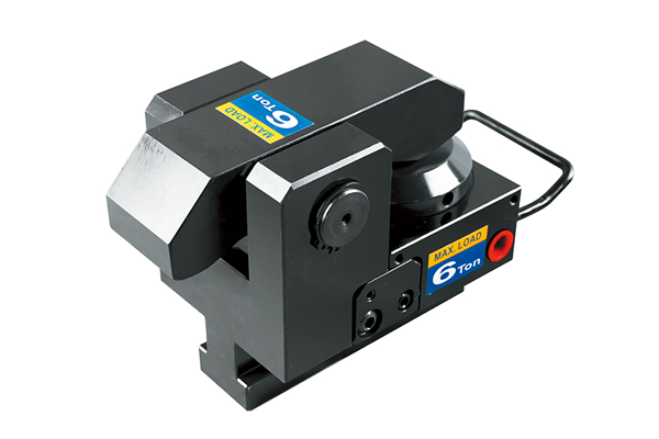
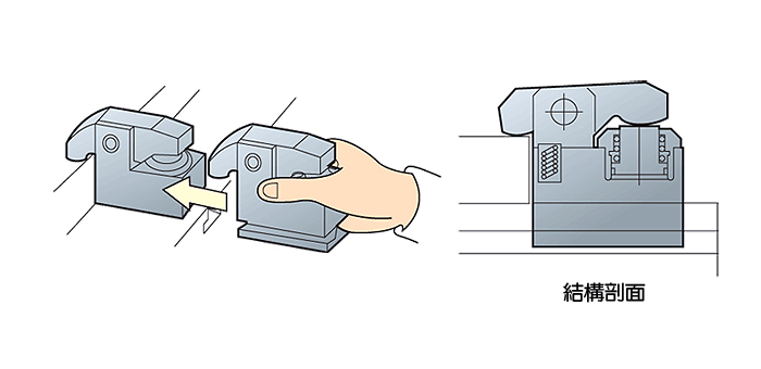
As this lever-type clamp does not require a U-slot on the die shoe it can be used in a wide range of applications. The TY type Die Clamps are machined to fit into the T-slot of the bolster for extra secure positioning. The flange-mount model Die Clamps can be bolted onto the bolster and the automatic slider model Die Clamps makes remote automatic operation possible.
Die Clamp Introduction
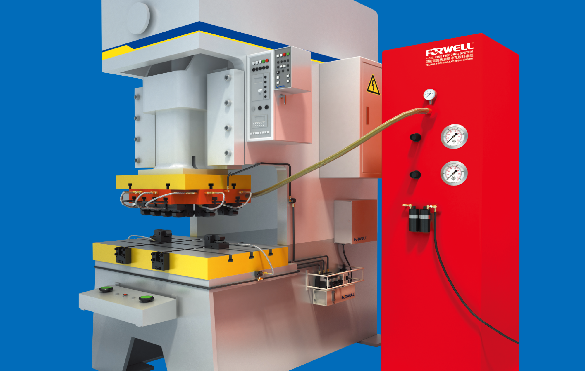
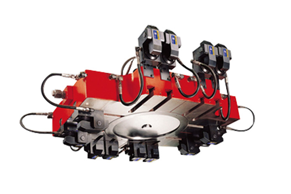
All Forwell Quick Mold Change Systems use high quality Die Clamps for very secure clamping, quick mold changing and safer operations. These clamps can fasten Molds whether they are changed vertically or horizontally.
There are also a range of different Die Clamps available to suit your injection molding or mold casting requirements. The TY type Die Clamps are machined to fit into the T-slot of the bolster for extra secure positioning. The flange-mount model Die Clamps can be bolted onto the bolster and the automatic slider model Die Clamps makes remote automatic operation possible.
Clamp Specifications
The following specifications can help you choose the appropriate clamp type in accordance with your injection molding requirements and production situation. Make sure of your production plans and production procedure before choosing your product to be sure of the product that best suits your needs.
| Mold Plate |
Mold Change Direction |
Clamping type |
Characteristics |
| No Union |
Vertically |
Moving Clamp |
Fixed in with T-slot |
| Union |
Vertically |
Fixed & Moving Clamp |
Clamp fixed or Moving on plate |
| Horizontally |
Fixed Clamp |
Install roller or sliding rail upon the plate. Use cart or mold exchange table for easy operation and the shortest possible mold changing time. |
TY Clamp Model Specifications
| Model |
Unit |
TY-1 |
TY-2 |
TY-4 |
TY-6 |
TY-10 |
TY-16 |
TY-25 |
| Tons Clamping (at 250Kg/cm2) |
tons |
1 |
2 |
4 |
6.3 |
10 |
16 |
25 |
| Full Stroke (X) |
mm |
6 |
7 |
7 |
8 |
8 |
7 |
8 |
| Clamping Stroke (Y) |
mm |
3 |
2 |
3 |
4 |
3 |
3 |
3 |
| Extra Stroke (Z) |
mm |
3 |
5 |
4 |
4 |
5 |
4 |
5 |
| Cylinder Capacity st Full Stroke |
cc |
2 |
6.5 |
13.2 |
22.3 |
37 |
61 |
93 |
Clamp Dimensions
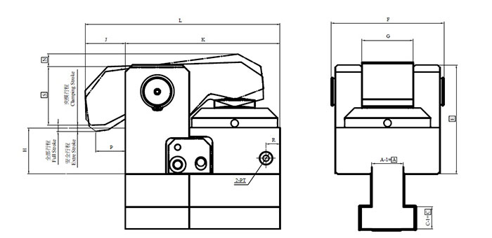
For a closer look at the exact dimensions of the TY series die clamps please see the following diagram and table.
| Model |
min.E |
F |
G |
J |
K |
L |
max.N |
P |
R |
min.S |
PT |
min.C |
min.A |
| TY-1 |
49.5 |
46 |
20 |
15 |
58 |
73 |
10 |
10 |
34 |
16.5 |
1/8 |
7 |
10 |
| TY-2 |
59 |
63 |
28 |
22 |
85 |
107 |
10 |
12.5 |
48 |
27 |
1/8 |
9.5 |
12.5 |
| TY-4 |
85 |
87 |
40 |
25 |
120 |
145 |
10 |
16 |
12 |
32 |
1/4 |
12 |
15 |
| TY-6 |
94 |
97 |
44 |
29.5 |
133 |
162.5 |
11 |
20 |
12 |
40 |
1/4 |
14 |
19 |
| TY-10 |
105 |
110 |
50 |
28 |
165 |
193 |
11 |
20 |
19 |
53 |
1/4 |
16.5 |
23 |
| TY-16 |
120 |
130 |
60 |
30 |
200 |
230 |
12 |
20 |
25 |
67 |
1/4 |
19 |
27 |
| TY-25 |
133 |
150 |
73 |
30 |
240 |
270 |
13 |
20 |
30 |
81 |
1/4 |
22 |
32 |
| Model |
A |
B |
C |
D |
Power Unit Models |
| TY-1 |
22 |
37 |
16 |
24 |
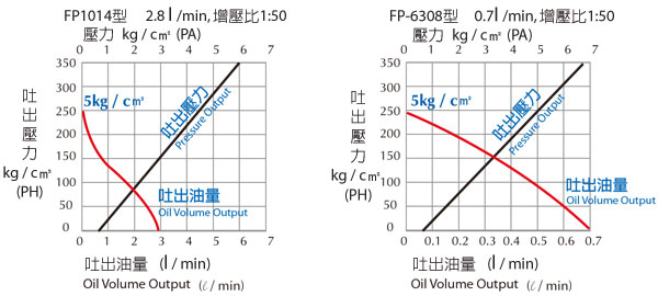
FP6308U-4-4C |
| TY-2 |
22 |
37 |
16 |
24 |
| TY-4 |
22 |
37 |
16 |
24 |
FP1014U-4-4C |
| TY-6 |
28 |
48 |
20 |
28 |
| TY-10 |
28 |
48 |
20 |
28 |
| TY-16 |
28 |
48 |
23 |
28 |
| TY-25 |
36 |
56 |
25 |
28 |
Die shoe thickness (h) available: 25, 30, 35, 40, 45, 50, 55, 60mm.
Before purchasing, please verify if the mold edge thickness (h) and T-slot (A.B.C.D.) have standard or special dimensions.

