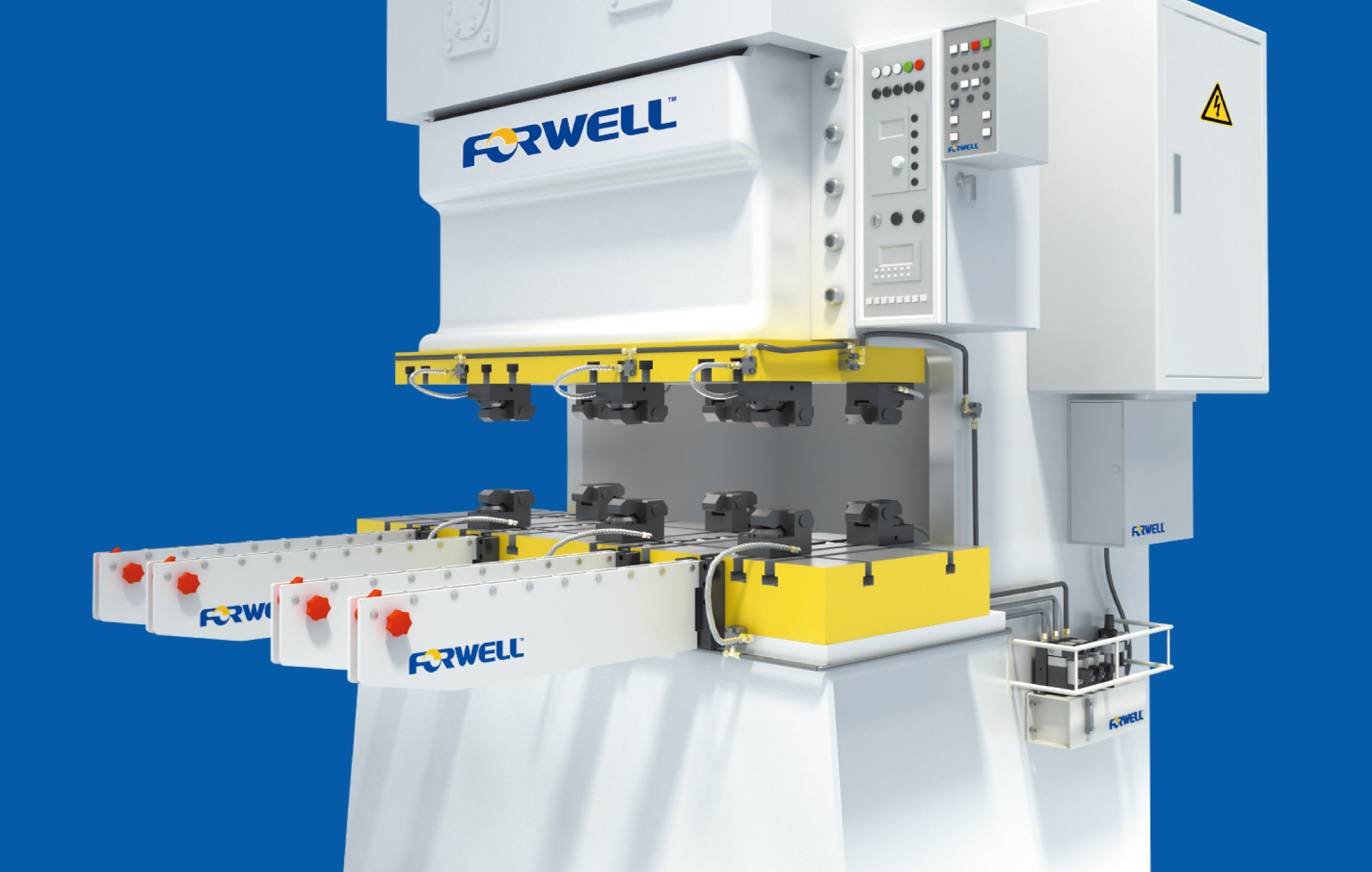
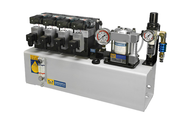
面對市場產品不斷推陳出新,少量多樣的市場需求已逐漸成為新時代的主流,當產品週期逐漸短縮也意味著高換模時代的來臨,企業導入快速換模系統已成為生產製造過程中重要的一環,在過去沖床製造業對於換模作業並不太重視常導致資源的浪費,為了協助業者有效的更換模具,富偉推出的沖床專用快速換模系統不僅可以減少轉換模具的時間在人力的配置也取得額外的優勢。
快速換模系統最主要是透過自動化的生產模式在換模過程中做到快速的更換模具,更換模具時除了需要高效率的速度外最重要的是精確的精度及可靠的安全度才是重要關鍵,富偉提供的快速換模系統除了能夠符合上述條件外,多年來不斷的提昇技術改良產品,從創立初期的單機使用,多機使用,到現在已成功發展到模具輸送換模台車系統,現階段更跨入模具自動化倉儲設備,與模具維修系統等,透過全方位的配套系統不僅可以做到安全快速的更換模具也提供了模具管理及儲存自動化等多項功能,真正為企業規劃出最符合效益的生產方式才是富偉永續經營的企業遠景。
富偉在業界建立多年專業的形象,率先取得多項國際認證,更自創品牌「FORWELL」行銷世界,未來富偉仍然會不斷投入心力於快速換模的研發,協助業界邁向自動化生產,使快速換模系統成為您自動化生產的好幫手。
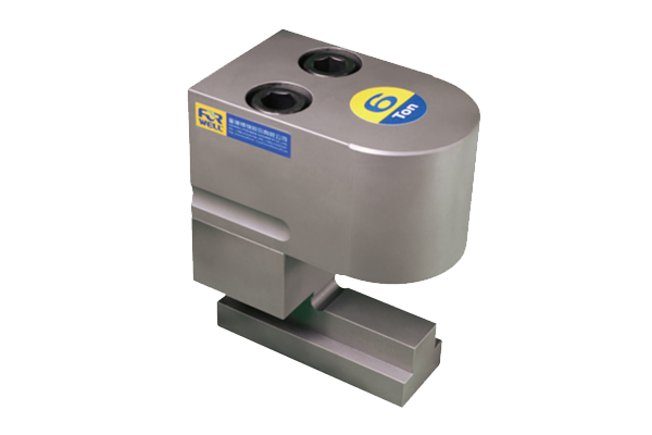
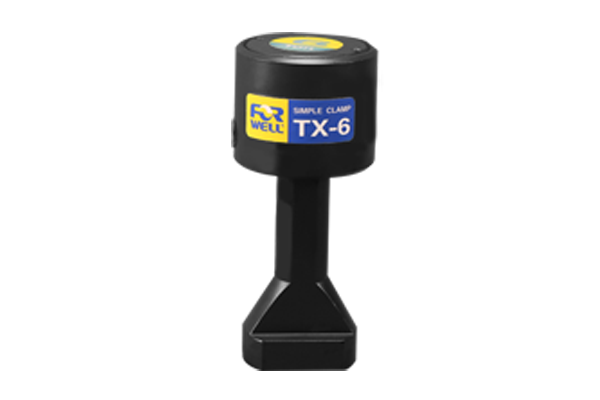
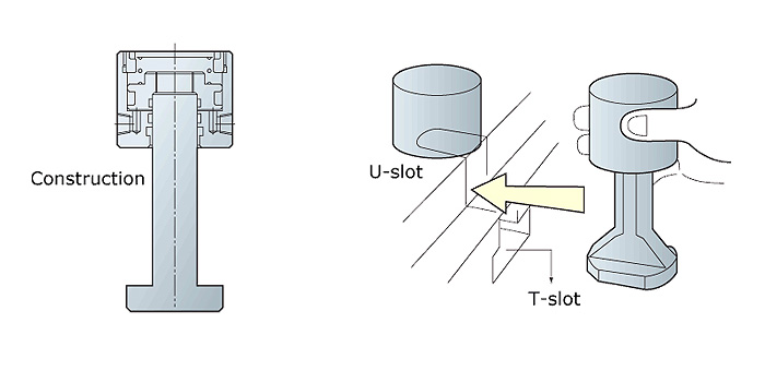
此型夾模器有節省空間的好處,但模沿須有"U"型溝供其夾持,其底部被製成適合在台盤"T"型槽滑動。
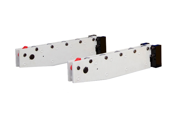
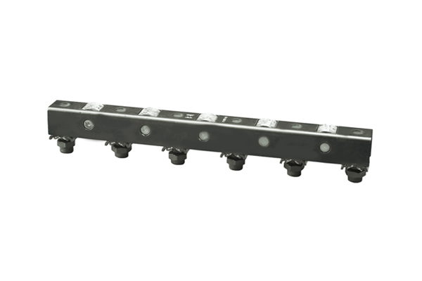
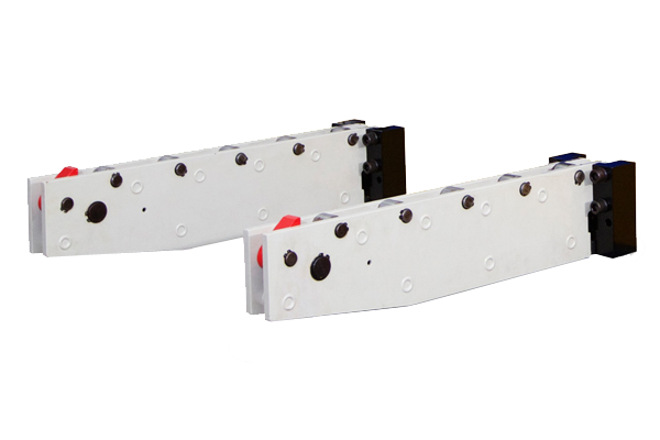
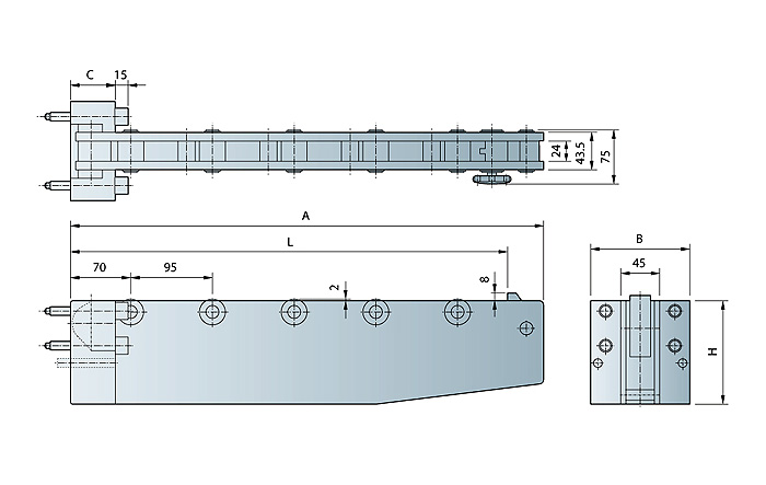
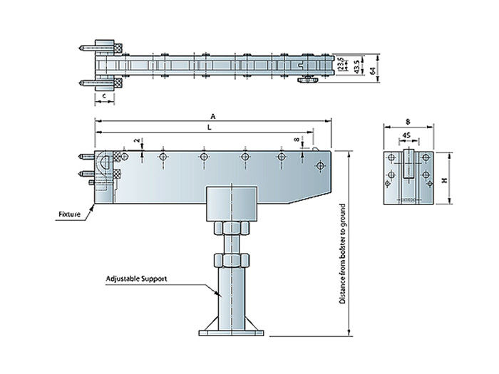
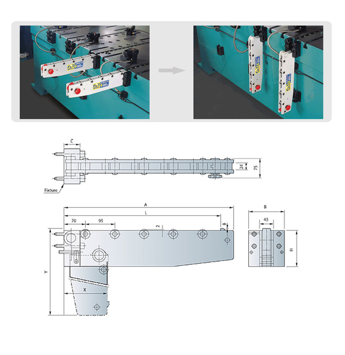
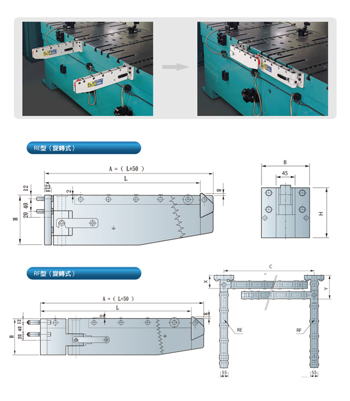
當您使用起重機或叉架昇降機作模具更換時,共有三種不同的型式設計,包括RC(移動式)、RD(折下式)與 RE/RF(旋轉式)系列,可供選用移模臂使用,可以使模具更容易的移到沖床台盤確實位置。
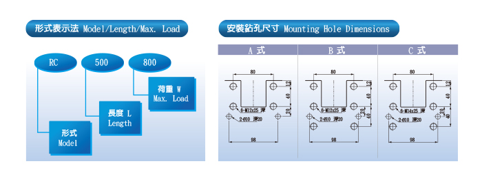
型號 | 模具引出長 (L) | 最大荷重 ( kg ) | 全長 ( A ) |
---|---|---|---|
RC-500-800 | 500 | 800 | 550 |
RC-500-1250 | 500 | 1250 | 550 |
RC-500-1600 | 500 | 1600 | 550 |
RC-700-600 | 700 | 600 | 750 |
RC-700-1000 | 700 | 1000 | 750 |
RC-800-800 | 800 | 800 | 850 |
RC-800-1600 | 800 | 1600 | 850 |
RC-800-2000 | 800 | 2000 | 850 |
RC-900-1600 | 900 | 1600 | 950 |
RC-1000-1600 | 1000 | 1600 | 1050 |
型號 | 固定座 | 滾輪數 | 安裝尺寸 | 固定座型式 | ||
---|---|---|---|---|---|---|
B | C | H | ||||
RC-500-800 | 115 | 46 | 120 | 5 | A 式 | RC-120 |
RC-500-1250 | 160 | RC-160 | ||||
RC-500-1600 | 50 | 200 | B 式 | RC-200 | ||
RC-700-600 | 46 | 120 | 7 | A 式 | RC-120 | |
RC-700-1000 | 160 | RC-160 | ||||
RC-800-800 | 160 | 8 | ||||
RC-800-1600 | 50 | 200 | B 式 | RC-200 | ||
RC-800-2000 | 200 | 9 | C 式 | RC-200 | ||
RC-900-900 | 200 | 9 | B 式 | RC-200 | ||
RC-1000-1600 | 10 |
型號 | 模具引出長 (L) | 最大荷重 ( kg ) | 全長 ( A ) |
---|---|---|---|
RC-1200-2500 | 1200 | 2500 | 1250 |
RC-1300-2500 | 1300 | 2500 | 1350 |
RC-1400-2500 | 1400 | 2500 | 1450 |
RC-1500-2500 | 1500 | 2500 | 1550 |
RC-1600-2500 | 1600 | 2500 | 1650 |
RC-1700-2500 | 1700 | 2500 | 1750 |
型號 | 固定座 | 滾輪數 | 安裝尺寸 | 固定座型式 | ||
---|---|---|---|---|---|---|
B | C | H | ||||
RC-1200-2500 | 115 | 45 | 120 | 14 | A 式 | RC-120 |
RC-1300-2500 | 15 | |||||
RC-1400-2500 | 17 | |||||
RC-1500-2500 | 18 | |||||
RC-1600-2500 | 19 | |||||
RC-1700-2500 | 20 |
型號 | 模具引出長 (L) | 最大荷重 ( kg ) | 全長 ( A ) |
---|---|---|---|
RD-500-800 | 500 | 800 | 550 |
RD-500-1250 | 500 | 1250 | 550 |
RD-500-1600 | 500 | 1600 | 550 |
RD-700-600 | 700 | 600 | 750 |
RD-700-1000 | 700 | 1000 | 750 |
RD-800-800 | 800 | 800 | 850 |
RD-800-1600 | 800 | 1600 | 850 |
RD-800-2000 | 800 | 2000 | 850 |
RD-900-900 | 900 | 900 | 950 |
RD-1000-1600 | 1000 | 1600 | 1050 |
型號 | 固定座 | 滾輪數 | 安裝尺寸 | 拆下時尺寸 | |||
---|---|---|---|---|---|---|---|
B | C | H | X | Y | |||
RD-500-800 | 115 | 52 | 120 | 5 | A 式 | 140 | 620 |
RD-500-1250 | 160 | 180 | 660 | ||||
RD-500-1600 | 200 | B 式 | 220 | 700 | |||
RD-700-600 | 120 | 7 | A 式 | 140 | 820 | ||
RD-700-1000 | 160 | 180 | 860 | ||||
RD-800-800 | 160 | 8 | B 式 | 180 | 960 | ||
RD-800-1600 | 200 | 220 | 1000 | ||||
RD-800-2000 | 200 | 9 | C 式 | 220 | 1000 | ||
RD-900-1600 | 200 | 9 | B 式 | 220 | 1100 | ||
RD-1000-1600 | 10 | 1200 |
型號 | 模具引出長 (L) | 最大荷重 ( kg ) | 全長 ( A ) |
---|---|---|---|
RE.RF-500-800 | 500 | 800 | 550 |
RE.RF-500-1250 | 500 | 1250 | 550 |
RE.RF-700-600 | 700 | 600 | 750 |
RE.RF-700-1600 | 700 | 1600 | 750 |
RE.RF-800-800 | 800 | 800 | 850 |
RE.RF-800-1600 | 800 | 1600 | 850 |
RE.RF-500-1600 | 500 | 1600 | 550 |
RE.RF-900-1600 | 900 | 1600 | 950 |
型號 | 固定座 | 滾輪數 | 安裝尺寸 | 拆下時尺寸 | |||
---|---|---|---|---|---|---|---|
B | C | H | X | Y | |||
RE.RF-500-800 | 525 | 115 | 120 | 5 | A 式 | 90 | 150 |
RE.RF-500-1250 | 525 | 160 | |||||
RE.RF-700-600 | 725 | 120 | 7 | ||||
RE.RF-700-1600 | 725 | 200 | 7 | B 式 | |||
RE.RF-800-800 | 825 | 160 | 8 | A 式 | |||
RE.RF-800-1600 | 825 | 200 | 8 | B 式 | |||
RE.RF-500-1600 | 525 | 5 | |||||
RE.RF-900-900 | 925 | 9 |
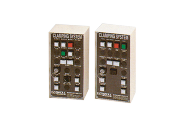
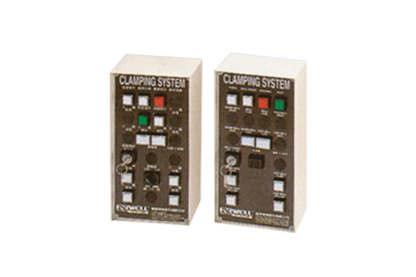
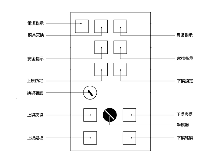
操作控制箱為本快速換模系統狀態顯示, 與功能操作介面,上半部(1~10)為顯 示與自動操作功能,下半部(11~17)為 手動操作功能按鍵。
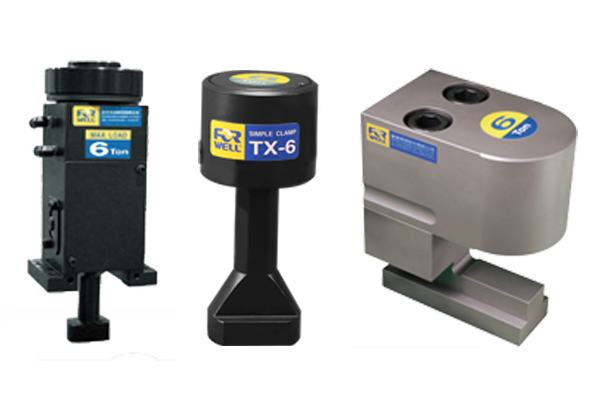
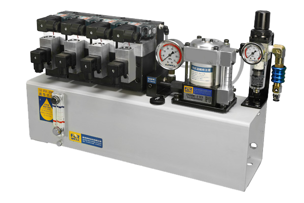
配合脫料能力配備不同夾模器,使更換模具簡單快速。 夾模器有效強力夾模,沖孔時模具不滑動。 動力源採用氣動泵組合,臨時停電或空氣壓消失時,夾模能長時間保持,節省換模時間使作業更安全,提高生產效率。
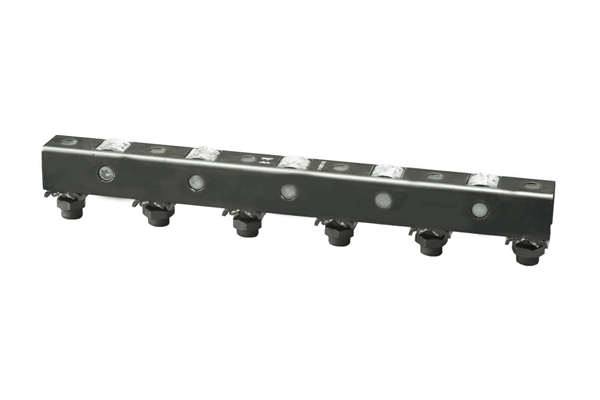
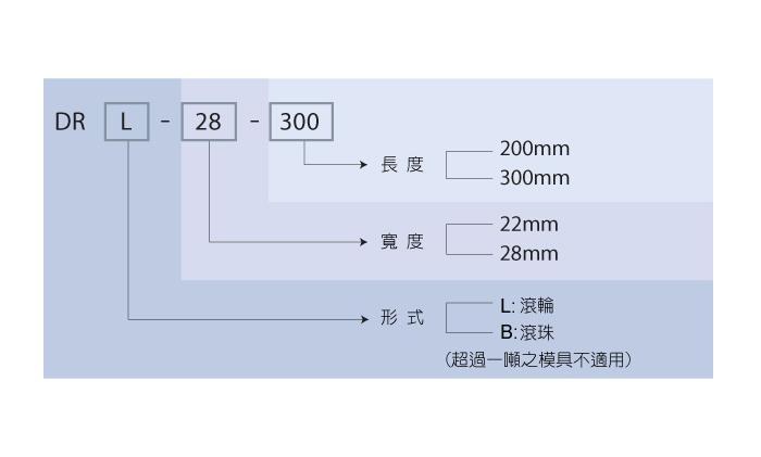
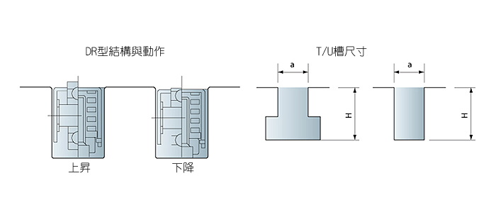
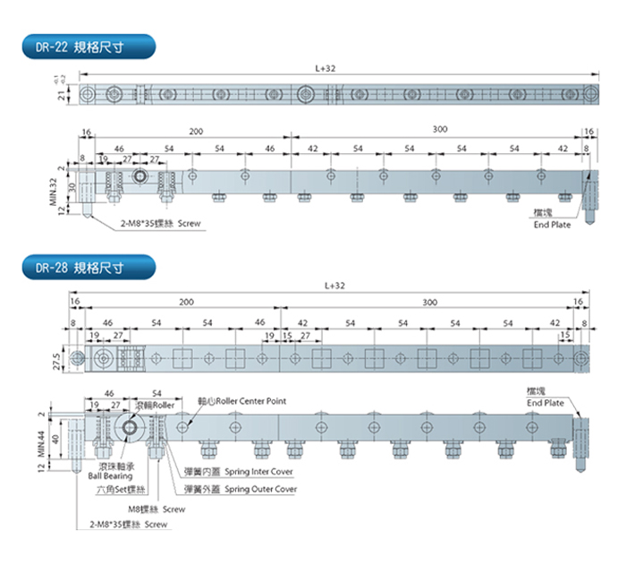
DR型舉模器可藉由填隙片的增減,很容易的適用不同尺寸的"T"型槽或"U"型槽。 其基本長度有200mm與300mm兩種尺寸,經過搭配使用,可產生每100mm的總度變化。
型號 | a | H |
---|---|---|
DR-22 | 22 | 33-43 |
DR-28 | 28 | 45-58 |
基本型式 | 寬度 (mm) | 長度 (mm) | 彈簧數量 (pcs) | 單一彈簧舉模力 (kgf) |
---|---|---|---|---|
DRL-22-200/DRB22-200 | 22 | 200 | 4 | 37.5 |
DRL-22-300/DRB22-300 | 22 | 300 | 6 | 37.5 |
DRL-28-200/DRB28-200 | 28 | 200 | 4 | 75 |
DRL-28-300/DRB28-300 | 28 | 300 | 6 | 75 |
* DRL-22/DRB-22 耐熱溫度80℃
* DRL-28/DRB-28 耐熱溫度150℃
單一舉模器最大舉模力 (kgf)
mm kgf 型號 |
200 | 300 | 400 | 500 | 600 | 700 | 800 | 900 | 1000 |
---|---|---|---|---|---|---|---|---|---|
DR-22 | 150 | 225 | 300 | 375 | 450 | 525 | 600 | 675 | 750 |
DR-28 | 300 | 450 | 600 | 750 | 900 | 1050 | 1200 | 1350 | 1500 |
單一舉模器最大舉模力 (kgf)
mm kgf 型號 |
1100 | 1200 | 1300 | 1400 | 1500 | 1600 | 1700 | 1800 | 1900 | 2000 |
---|---|---|---|---|---|---|---|---|---|---|
DR-22 | 825 | 900 | 975 | 1050 | 1125 | 1200 | 1275 | 1350 | 1425 | 1500 |
DR-28 | 1650 | 1800 | 1950 | 2100 | 2250 | 2400 | 2550 | 2700 | 2850 | 3000 |
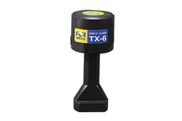
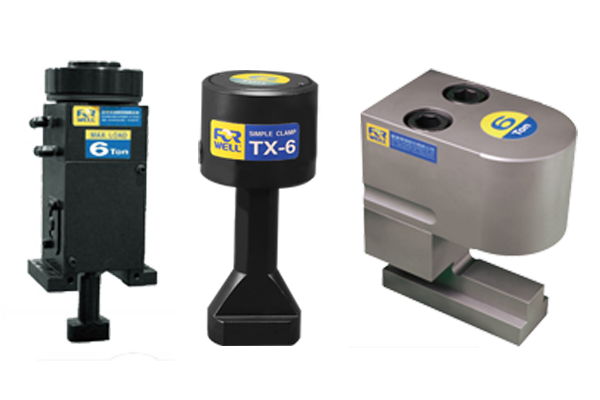
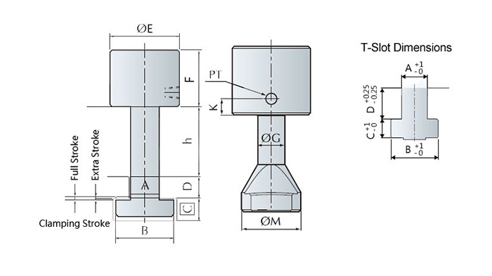
This compact, space saving, piston type clamp requires U-slots on the die shoe. The clamp leg is machined to fit the T-slot on the bolster. With the TX 型夾模器 automatic slide model remote control is made possible.
型號 | Unit | TX-1 | TX-2 | TX-4 | TX-6 | TX-10 | TX-16 | TX-25 |
---|---|---|---|---|---|---|---|---|
夾模器ing Farce(at 250kgf/cm2) | tons | 1 | 2 | 4 | 6.3 | 10 | 16 | 25 |
Full Stroke (X) | mm | 5 | 8 | 8 | 8 | 8 | 8 | 8 |
夾模器ing Stroke (Y) | mm | 2.5 | 4 | 3 | 3 | 3 | 3 | 3 |
Extra Stroke (Z) | mm | 2.5 | 4 | 5 | 5 | 5 | 5 | 5 |
Cylinder Capacity at Full Stroke | cc | 2.7 | 6.5 | 13 | 21 | 32 | 54 | 84 |
Extra stroke is the difference between full stroke and clamping stroke with extra space allowed for safe operation.
型號 | E | F | G | H | K | MIN. | PT |
---|---|---|---|---|---|---|---|
TX-1 | 38 | 37 | 14 | 35 | 11 | 8 | 1/8 |
TX-2 | 53 | 52.5 | 18 | 38 | 12 | 8 | 1/8 |
TX-4 | 68 | 61.5 | 23 | 59 | 15 | 10 | 1/4 |
TX-6 | 78 | 68 | 27 | 59 | 16 | 14 | 1/4 |
TX-10 | 98 | 71 | 38 | 79 | 16 | 17 | 1/4 |
TX-16 | 127 | 78.5 | 48 | 88 | 16 | 20 | 1/4 |
TX-25 | 148 | 100 | 58 | 98 | 15 | 23 | 1/4 |
Die shoe thickness(h)Classify:25、30、35、40、45、50、55、60mm.
Before purchase, please verify mold edge thickness (h) and T-slot (A.B.C.D.) has standard or special dimensions.
型號 | A | B | C | D | 動力源組合 型號s |
---|---|---|---|---|---|
TX-1 | 22 | 37 | 16 | 24 | FP6308U-口-口 |
TX-2 | 22 | 37 | 16 | 24 | |
TX-4 | 22 | 37 | 16 | 24 | |
TX-6 | 28 | 48 | 20 | 28 | |
TX-10 | 28 | 48 | 20 | 28 | FP1014U-口-口 |
TX-16 | 28 | 48 | 23 | 28 | |
TX-25 | 36 | 56 | 25 |
Die shoe thickness(h)Classify:25、30、35、40、45、50、55、60mm.
Before purchase, please verify mold edge thickness (h) and T-slot (A.B.C.D.) has standard or special dimensions.
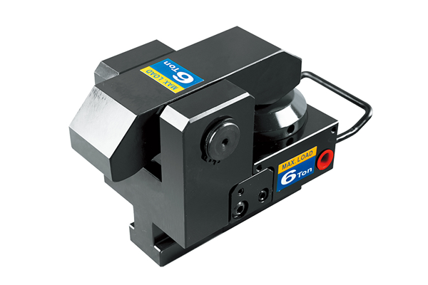
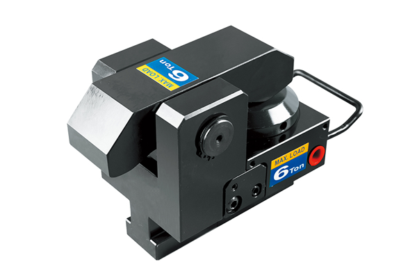
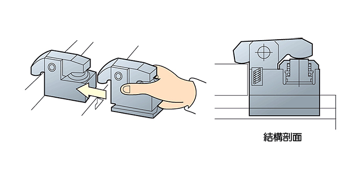
As this lever-type clamp does not require a U-slot on the die shoe it can be used in a wide range of applications. The TY type 夾模器 are machined to fit into the T-slot of the bolster for extra secure positioning. The flange-mount model 夾模器 can be bolted onto the bolster and the automatic slider model 夾模器 makes remote automatic operation possible.
All Forwell 射出機壓鑄機快速換模系統s use high quality 夾模器 for very secure clamping, quick mold changing and safer operations. These clamps can fasten Molds whether they are changed vertically or horizontally.
There are also a range of different 夾模器 available to suit your injection molding or mold casting requirements. The TY type 夾模器 are machined to fit into the T-slot of the bolster for extra secure positioning. The flange-mount model 夾模器 can be bolted onto the bolster and the automatic slider model 夾模器 makes remote automatic operation possible.
以下的規格表能夠協助您找到適合的夾模型號,以搭配您的模具類型。請在選擇前確認您的生產線情況以及流程細節,以得出最優化的結果。
Mold Plate | Mold Change Direction | 夾模器ing type | Characteristics |
---|---|---|---|
No Union | Vertically | 活動側 夾模器 | 固定側 in with T-slot |
Union | Vertically | 固定側 & 活動側 夾模器 | 夾模器 fixed or 活動側 on plate |
Horizontally | 固定側 夾模器 | Install roller or sliding rail upon the plate. Use cart or mold exchange table for easy operation and the shortest possible mold changing time. |
型號 | Unit | TY-1 | TY-2 | TY-4 | TY-6 | TY-10 | TY-16 | TY-25 |
---|---|---|---|---|---|---|---|---|
機台能力s 夾模器ing (at 250Kg/cm2) | tons | 1 | 2 | 4 | 6.3 | 10 | 16 | 25 |
Full Stroke (X) | mm | 6 | 7 | 7 | 8 | 8 | 7 | 8 |
夾模器ing Stroke (Y) | mm | 3 | 2 | 3 | 4 | 3 | 3 | 3 |
Extra Stroke (Z) | mm | 3 | 5 | 4 | 4 | 5 | 4 | 5 |
Cylinder Capacity st Full Stroke | cc | 2 | 6.5 | 13.2 | 22.3 | 37 | 61 | 93 |
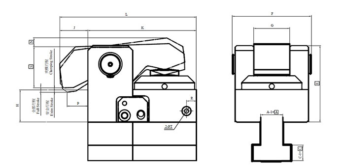
For a closer look at the exact dimensions of the TY series die clamps please see the following diagram and table.
型號 | min.E | F | G | J | K | L | max.N | P | R | min.S | PT | min.C | min.A |
---|---|---|---|---|---|---|---|---|---|---|---|---|---|
TY-1 | 49.5 | 46 | 20 | 15 | 58 | 73 | 10 | 10 | 34 | 16.5 | 1/8 | 7 | 10 |
TY-2 | 59 | 63 | 28 | 22 | 85 | 107 | 10 | 12.5 | 48 | 27 | 1/8 | 9.5 | 12.5 |
TY-4 | 85 | 87 | 40 | 25 | 120 | 145 | 10 | 16 | 12 | 32 | 1/4 | 12 | 15 |
TY-6 | 94 | 97 | 44 | 29.5 | 133 | 162.5 | 11 | 20 | 12 | 40 | 1/4 | 14 | 19 |
TY-10 | 105 | 110 | 50 | 28 | 165 | 193 | 11 | 20 | 19 | 53 | 1/4 | 16.5 | 23 |
TY-16 | 120 | 130 | 60 | 30 | 200 | 230 | 12 | 20 | 25 | 67 | 1/4 | 19 | 27 |
TY-25 | 133 | 150 | 73 | 30 | 240 | 270 | 13 | 20 | 30 | 81 | 1/4 | 22 | 32 |
型號 | A | B | C | D | 動力源組合 型號s |
---|---|---|---|---|---|
TY-1 | 22 | 37 | 16 | 24 | FP6308U-4-4C |
TY-2 | 22 | 37 | 16 | 24 | |
TY-4 | 22 | 37 | 16 | 24 | FP1014U-4-4C |
TY-6 | 28 | 48 | 20 | 28 | |
TY-10 | 28 | 48 | 20 | 28 | |
TY-16 | 28 | 48 | 23 | 28 | |
TY-25 | 36 | 56 | 25 | 28 |
Die shoe thickness (h) available: 25, 30, 35, 40, 45, 50, 55, 60mm.
Before purchasing, please verify if the mold edge thickness (h) and T-slot (A.B.C.D.) have standard or special dimensions.
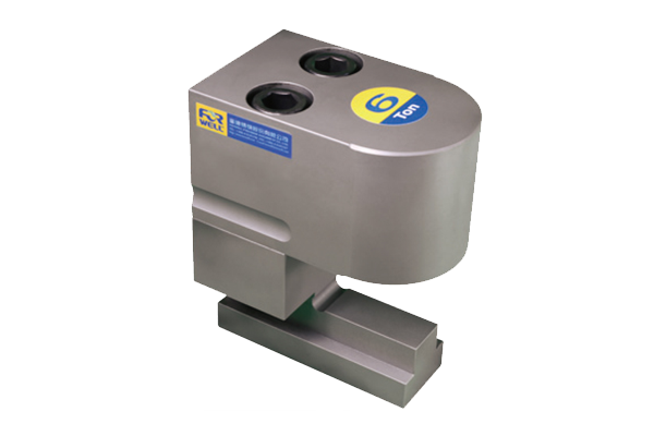
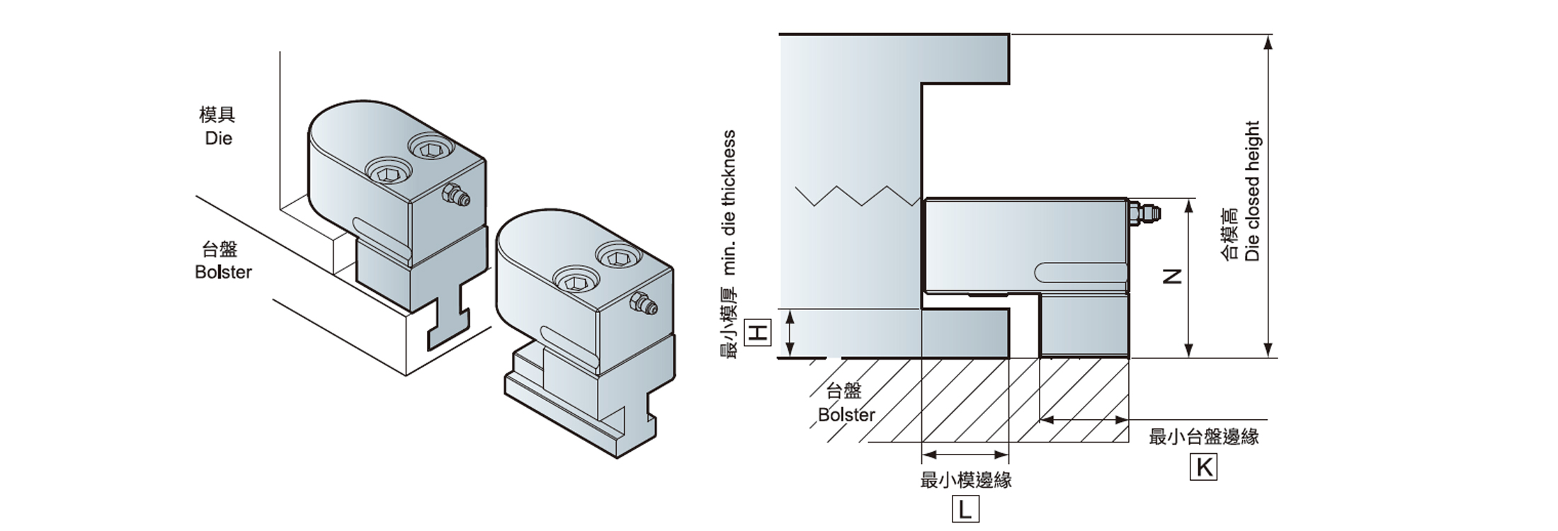
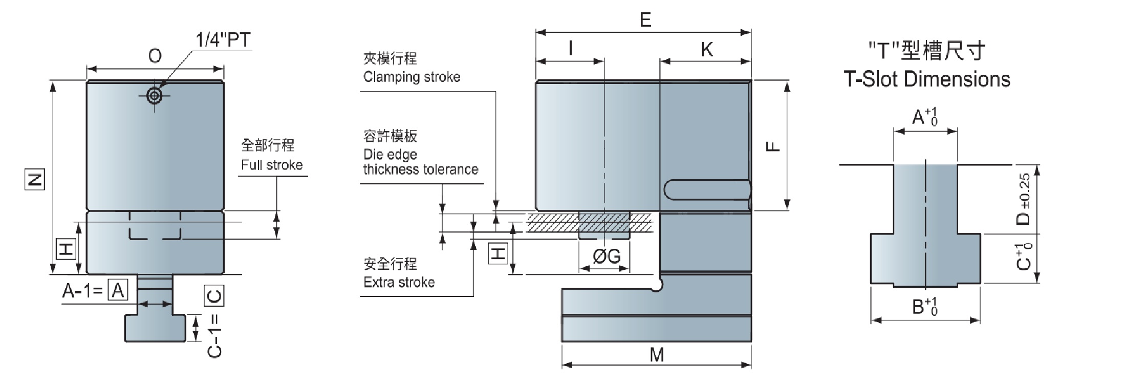
This vertical type clamp does not require a U-slot on the die shoe.The clamping stroke will be longer.
型號 | TD-2 | TD-4 | TD-6 | TD-10 |
---|---|---|---|---|
夾模器ing Force ( at 250 kg / cm2 ) ( tons ) | 2 | 4 | 6.3 | 10 |
Full Stroke ( X ) ( mm ) | 13 | 15 | 15 | 20 |
Flamping Stroke ( Y ) ( mm ) | 9 | 10 | 10 | 15 |
Extra Stroke ( Z ) ( mm ) | 4 | 5 | 5 | 5 |
Cylinder Capacity st Full Stroke ( cc ) | 12.5 | 30 | 42.5 | 89 |
Extra stroke is the difference between full stroke and clamping stroke with extra space allowed for safe operation.
型號 | min.H | min.L | min.K |
---|---|---|---|
TD-2 | 15 | 38.5 | 50 |
TD-4 | 24 | 54 | 58 |
TD-6 | 29 | 59 | 63 |
TD-10 | 29 | 72 | 70 |
Notice if ”N ”size is suitable for the die in closed condition.
型號 | E | F | G | I | K | M | O | min.N | min.A | min.C | A | B | C | D | 動力源組合 |
---|---|---|---|---|---|---|---|---|---|---|---|---|---|---|---|
TD-2 | 107 | 57 | 17 | 30 | 50 | 102 | 61 | F+25 | 12.5 | 9.5 | 22 | 37 | 16 | 24 | FP6308U-☐-☐ |
TD-4 | 130 | 63 | 28 | 40 | 58 | 120 | 80 | F+35 | 15 | 12 | 22 | 37 | 16 | 24 | FP1014U-☐-☐ |
TD-6 | 145 | 68 | 28 | 45 | 63 | 130 | 90 | F+40 | 19 | 14 | 28 | 48 | 20 | 28 | |
TD-10 | 165 | 92.5 | 39 | 52.5 | 70 | 145 | 105 | F+45 | 23 | 16.5 | 28 | 48 | 20 | 28 |
Before purchase, please verify mold edge thickness (h) and T-Slot(A.B.C.D) has standard or special dimensions.